Tiger Paw Javelin Setup Guide
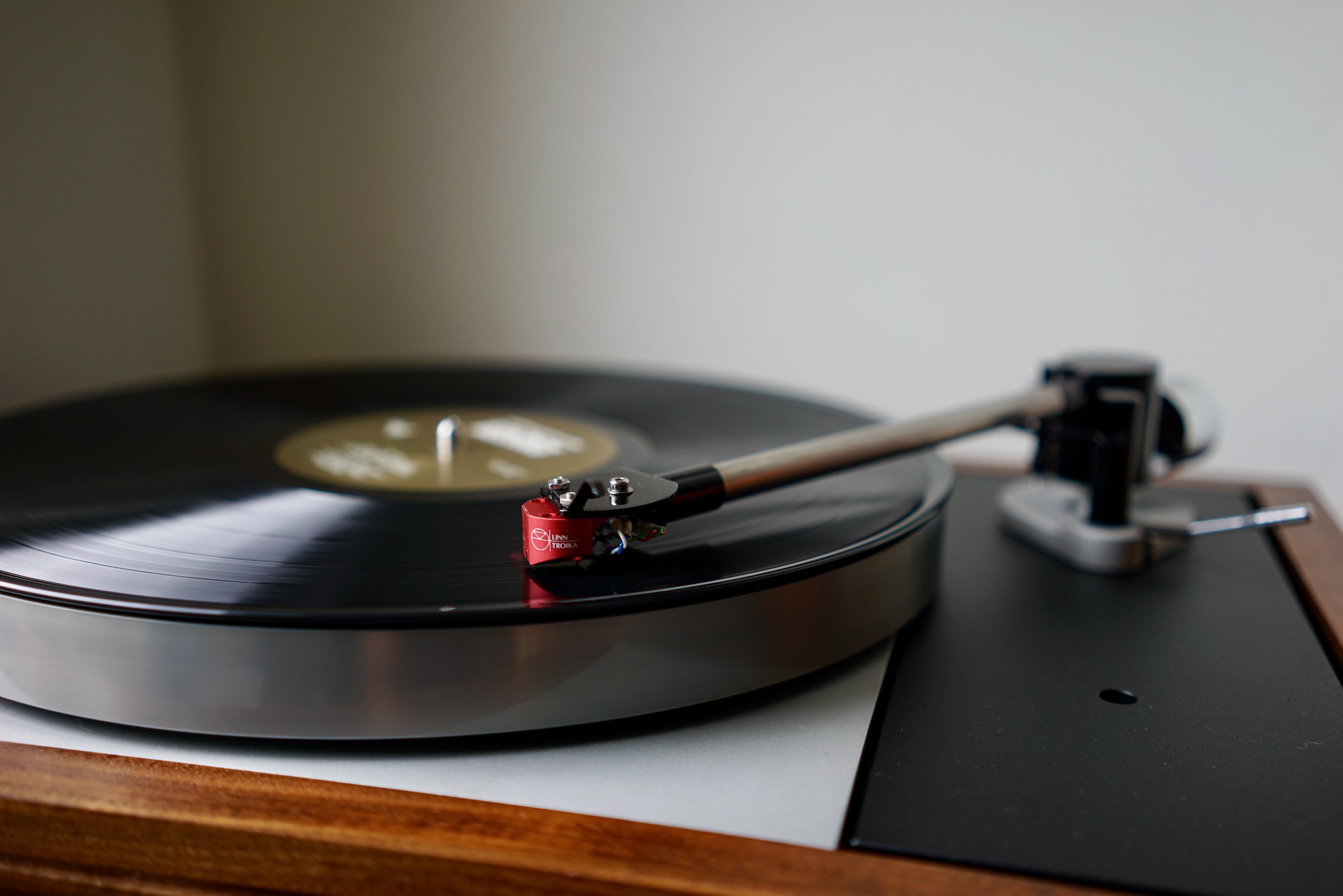
For reasons I describe in my LP12MF listening test, I’m a fan of the Tiger Paw Javelin — an attempt at updating the astounding and beautiful Naim Aro tonearm. But since Tiger Paw seems to have shut down shortly after the Javelin was released, there is no official manual for setting up the arm. On the one hand, since only about 30 of these things exist, this isn’t quite a disaster. On the other, Javelins are really tricky to set up, so for those of us fortunate enough to own one, a manual would be really handy.
Very luckily for me, the dealer I bought my Javelin from — Rick Duplisea of The Audio Alternative in Colorado — wrote out a very detailed instruction guide for his customers. Also luckily, several members of the AudioFlat forum have Javelins, and we’ve been having a lively conversation about how to install the arm.
What you’ll find below is my adaptation of Rick’s manual, incorporating feedback and suggestions from AudioFlat members and Javelin users @YNWaN and @VTA. I’ve tried to illustrate everything with my own photos. Rick Duplisea has kindly allowed me to adapt and republish his instructions here.
Here we go.
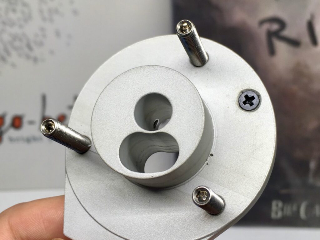
Install the three threaded rods into the bottom of the arm base.
Use a drop of blue thread locker for each threaded rod. Do not over-tighten; you don’t want to strip the aluminum threads in the arm base. (It’s possible that the aluminum used in the Javelin is a bit soft; I’ve had some issues with stripping threads.)
Make sure that the screw holding the anti-skate pillar is properly tightened.
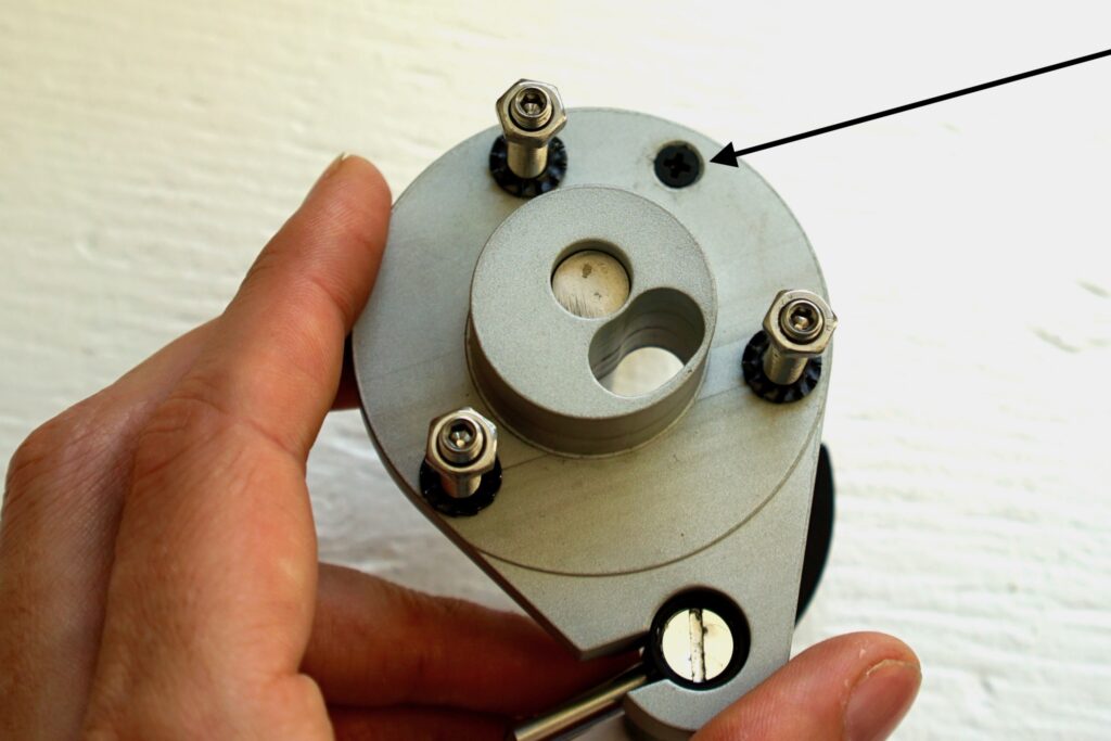
This screw threads into a blind threaded section in the silver anti-skate pillar. If it’s not tightened sufficiently, the anti-skate pillar will be loose and wobbly. (This was the case with mine when I received it.) Again, don’t over-tighten.
Insert arm base into the armboard.
The Javelin arm base needs a flush-mount Linn armboard. The Keel, with its integrated Ekos collar, won’t work.
You will find the collar/base can be rotated very slightly at this point with the bolts having some room in the armboard holes. Rotate the base so that the front will end up a little further from the record at playback. This is not necessary for use but will provide a bit more working space to cue your arm during record flips and swaps that you will find welcome.
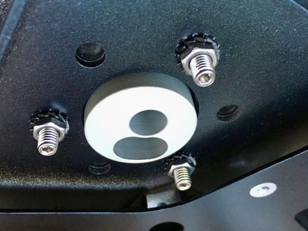
Use the three nuts with lock washers pressed against the underside of the armboard.
Get each screw finger tight, then slowly tighten each screw one turn. Getting one screw too tight too soon means your arm base won’t be absolutely flat on the armboard — bad news.
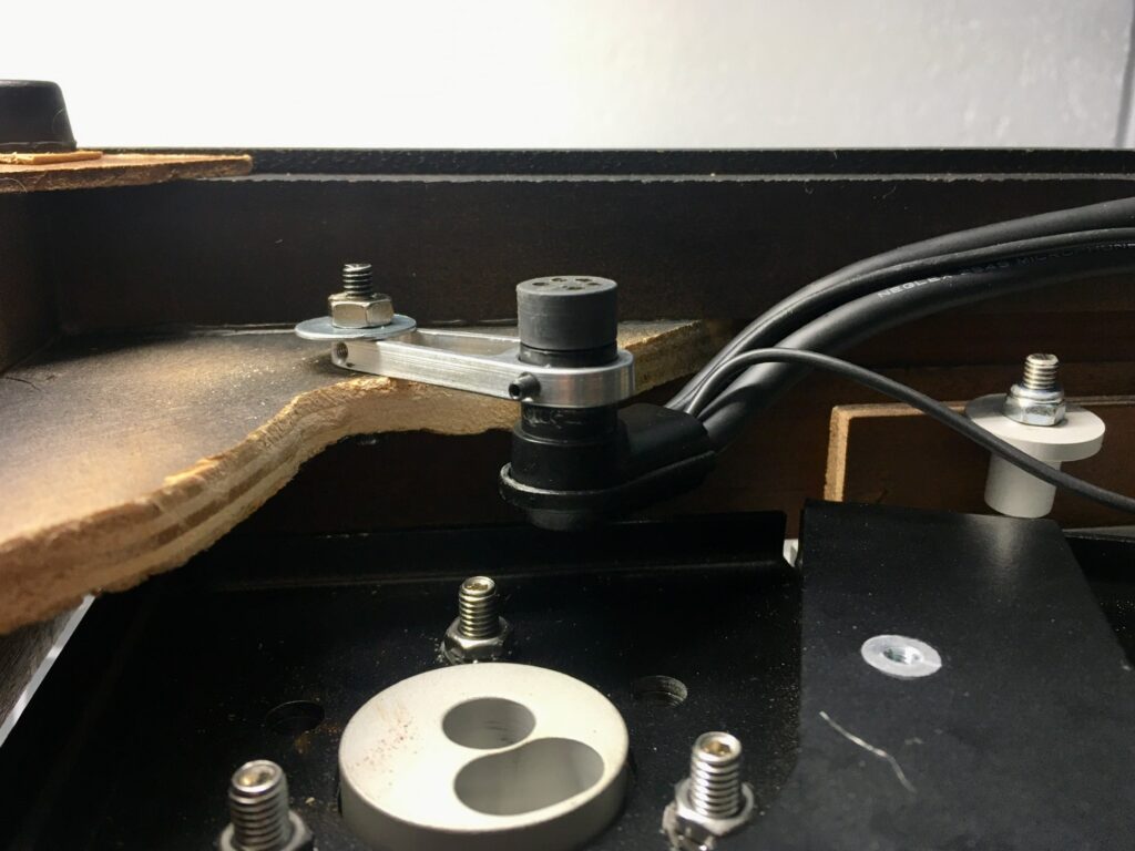
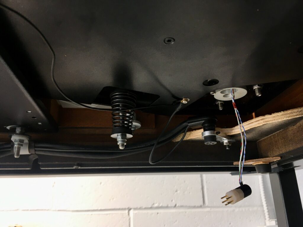
Attach the arm mounting bracket to the LP12 plinth.
The tonearm lead must be fixed to a metal mounting bracket that attaches to a hole you’ll need to drill in the corner brace nearest to the tonearm base.
Before drilling the hole, dry-fit everything to make sure that there is sufficient clearance for both arm leads — the tonearm lead to your phono preamp, and the internal leads to the cartridge — so that they don’t interfere with the suspension. Also make sure that you will end up with the cable attachment point in a place you can access it with your turntable base installed. (I don’t use one, so I can’t provide a photo of that.)
Drill a hole and attach the bracket as shown, from “above” (from this vantage point) the corner brace, pointing up. Adjust the height of the DIN connector so that you have clearance from the underside of the armboard and from the base plate. Fix the DIN connector on the tonearm lead in place with the grub screw.
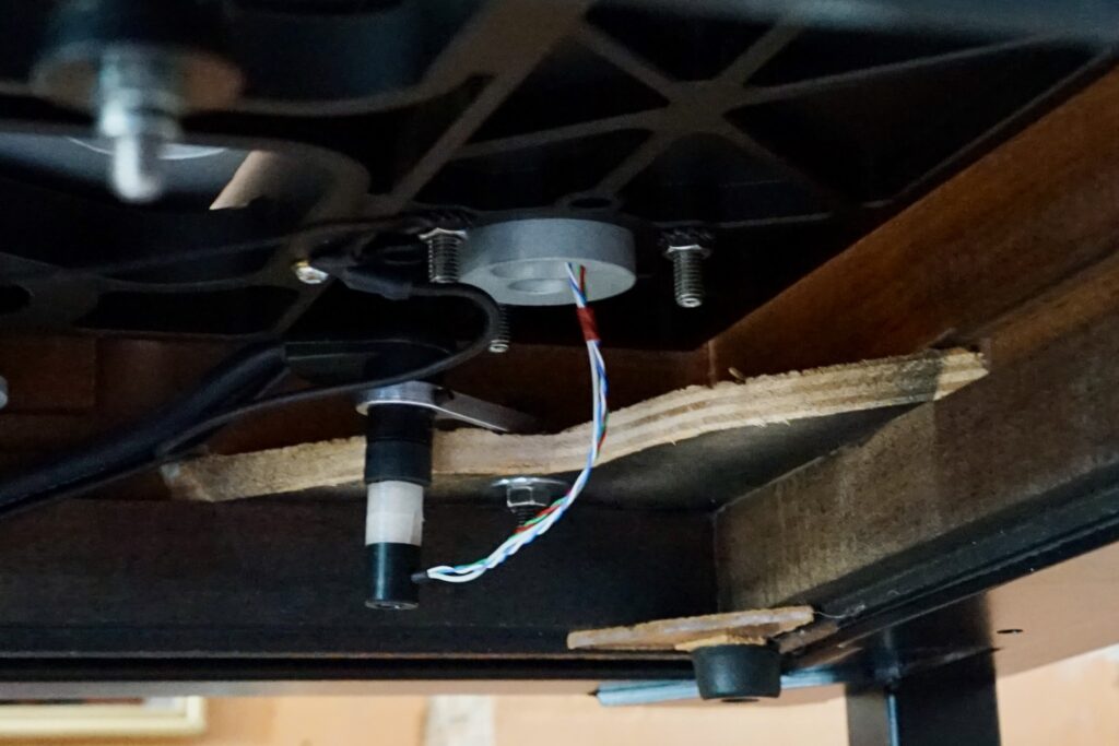
While you’re at it, attach the grounding screw to the terminal on the subchassis.
Really make sure that there is clearance for the suspension before proceeding to the next step.
The tonearm lead will eventually attach as shown below. (This is a great system, which significantly reduces the hassle of “cable dressing” to get a nice bounce on the LP12).
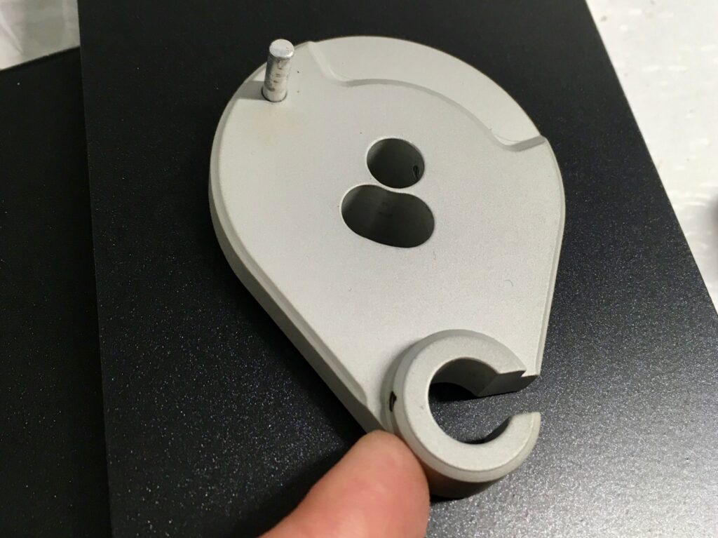
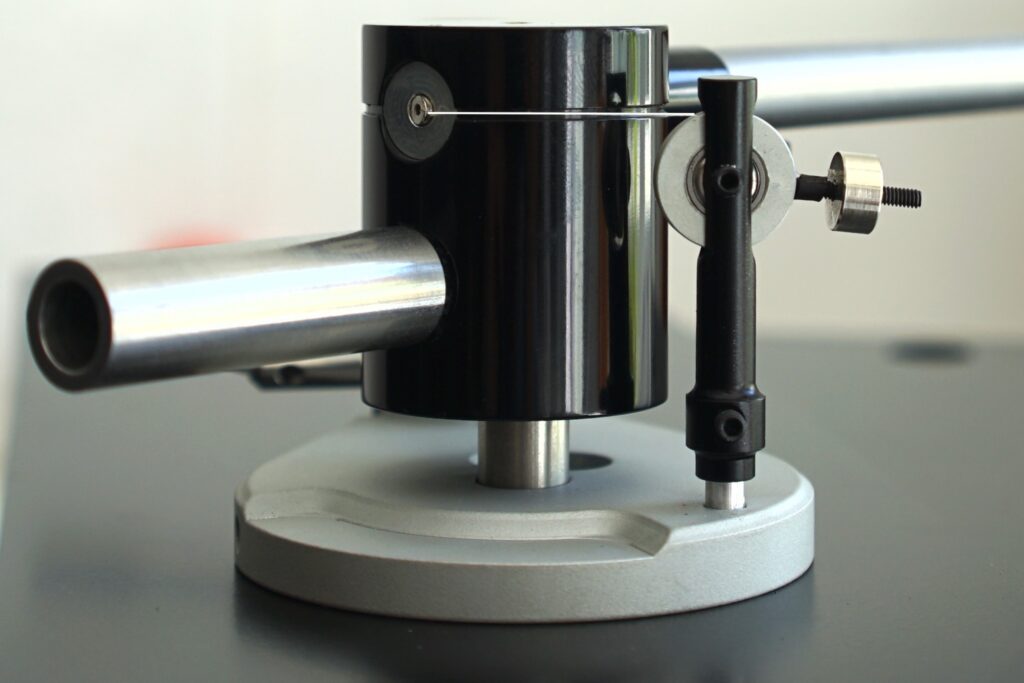
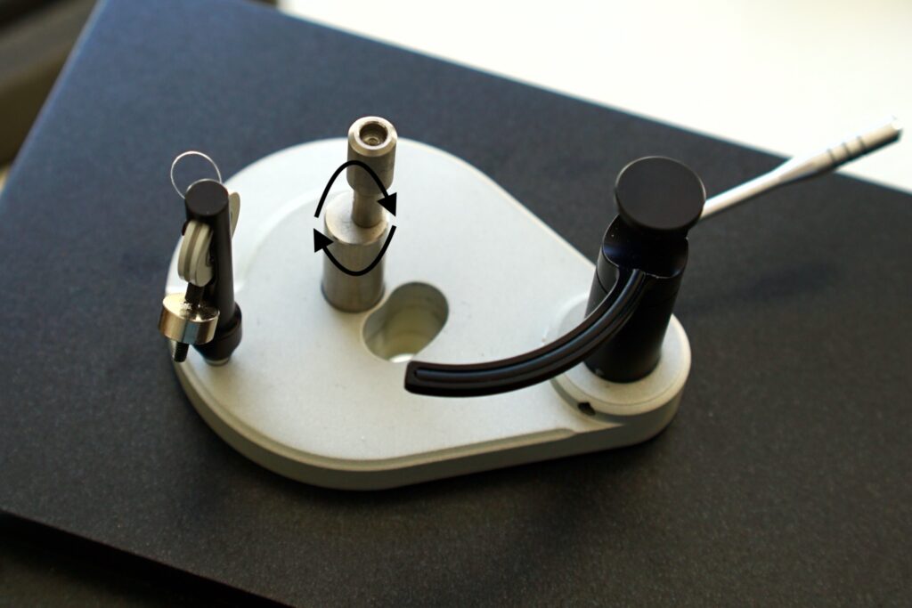
Insert main bearing pillar into arm base.
Note that the bearing pillar is eccentric, allowing for later adjustment to allow for final cartridge overhang.
Snug the hex grub screw on the side of the base to hold the bearing pilar in place. Do not over-tighten.
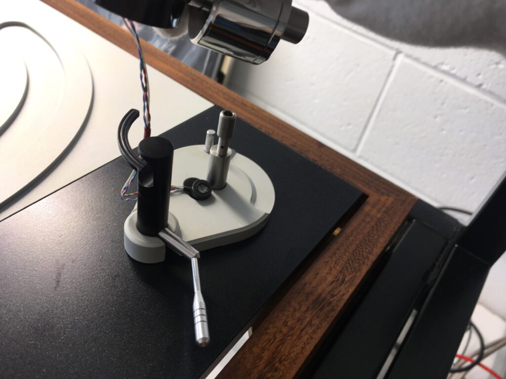
Install arm cue lifter in the arm base.
Orient the cue lifter so that the that cue lifter is centred within its slot in the arm base. Insert the lift all the way down to arm board, and barely snug grub screw holding it in place. Even a slight over-tightening will impair the cue from lowering properly to release the tone arm from its rest.
For some “short” cartridges, like the Linn Troika, it may not be possible to get the the arm lift low enough to allow for proper adjustment of Vertical Tracking Angle. If this is the case for your cartridge, you will either need to drill a hole through the armboard to accommodate the pillar or use spacers between the head shell and top of the cartridge to increase its height.
Install the counterweight.
Install the friction fit counterweight to rear of tone arm. Note that that it is eccentric, giving the ability to adjust azimuth and tracking force at the same time. The cartridge should be installed at this point.
Install the arm on the pivot.
When installing the arm, note that the arm cup has a center pin that fits within the pivot housing, engaging the cup at the top of the bearing rod.
Adjust the height of the main bearing pillar so that the arm tube is close to parallel with the record surface. This will be an iterative process; every time you want to adjust the height of the arm (VTA), you will need to remove the arm.
When you’re finished adjusting, don’t forget to drop the arm lead’s plug down through the slot in front of the bearing mount hole. (I always do!)
Next, you can set the vertical tracking force (VTF), by moving the counterweight toward or away from the pivot. Consider attaching the extra weight that comes with the Javelin if you find that your counterweight is too far from the pivot.
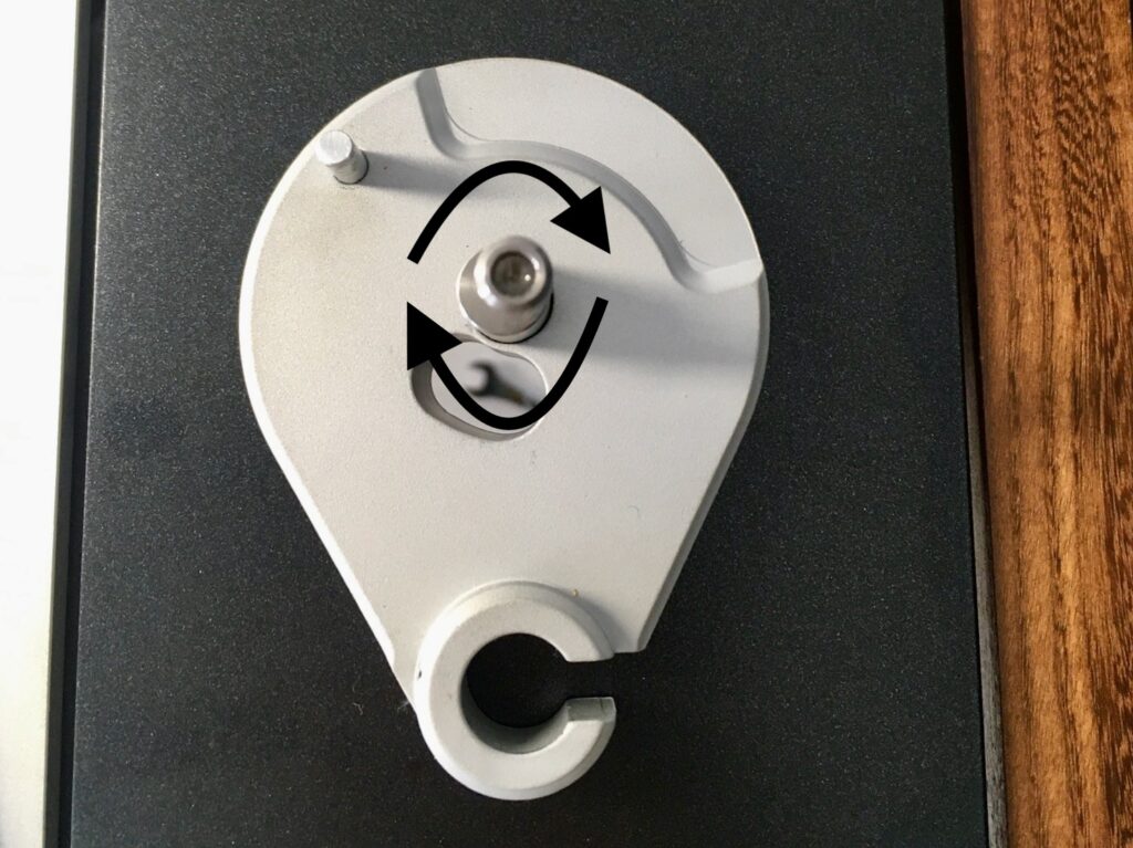
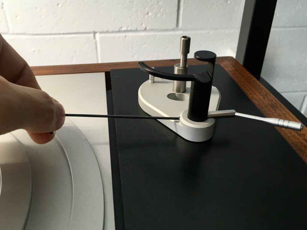
Set up the anti-skate system.
Slide the outer anti-skate pillar into the silver inner pillar.
Follow the mono-filament thread on the anti-skate wheel to a tiny magnet that attaches to the back center of the arm cup.
The height of the anti-skate pulley should be set so that the thread coming from the bearing housing is horizontal — not going up, or down, to the pulley. (White line added for clarity above.)
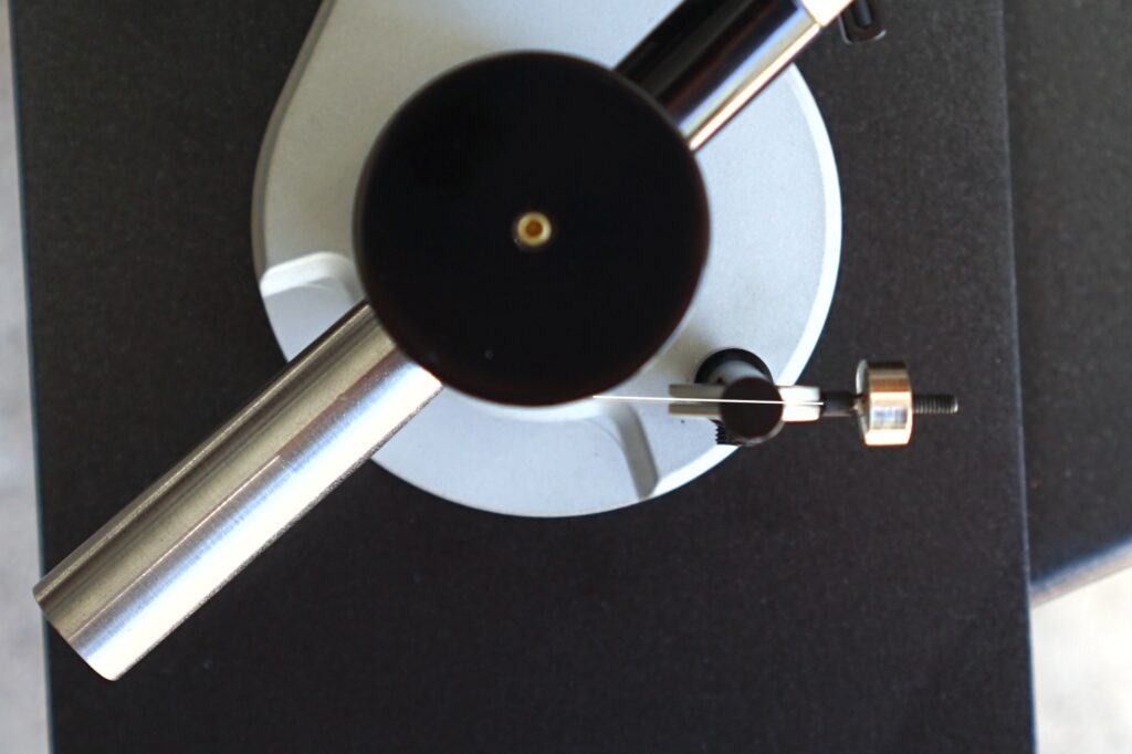
Then, when looking from above the thread must move in a straight line across the pulley and not approach the groove in it at an angle. (Again, white line added for clarity above.)
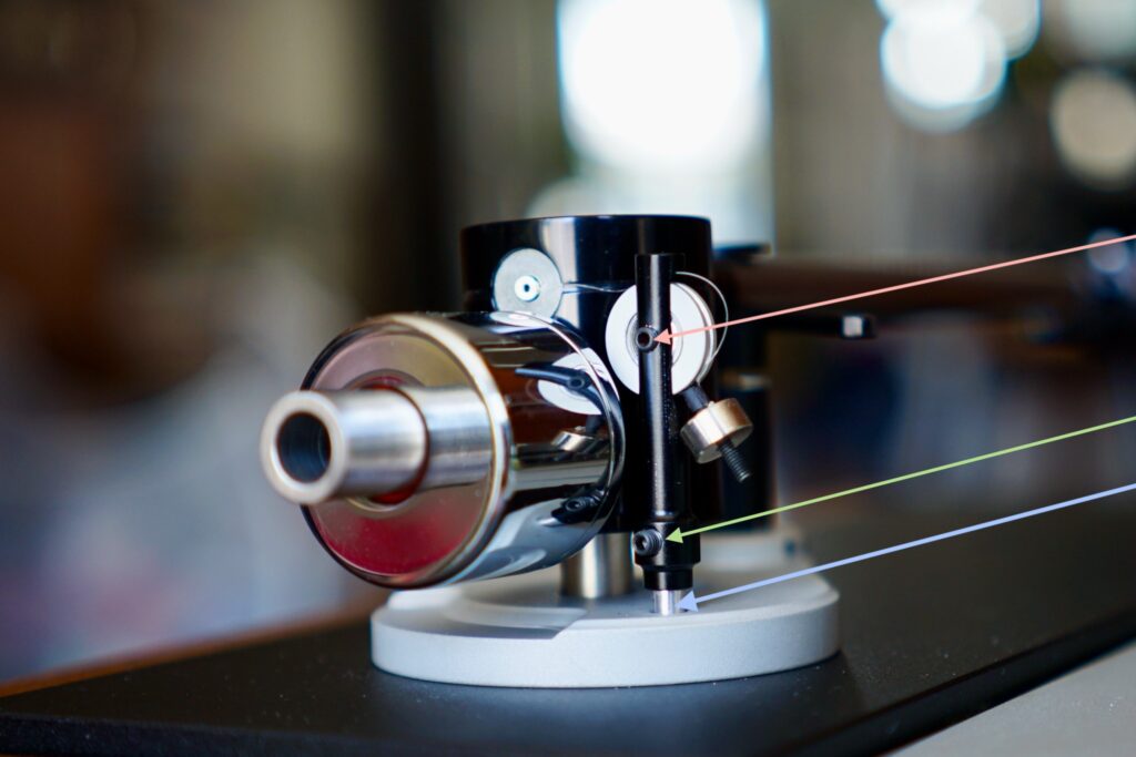
When this is correct, tighten the grub screw (green arrow) to lock the pillar in place — but be very careful not to over-tighten, as the aluminum threads will easily strip (I know this all too well). The same is true of the pulley grub screw (pink arrow): do not over-tighten; it strips very easily.
Set the azimuth.
This is done by rotating the eccentric counterweight. Be careful not to move the counterweight forward or backward, as this will affect the tracking force.
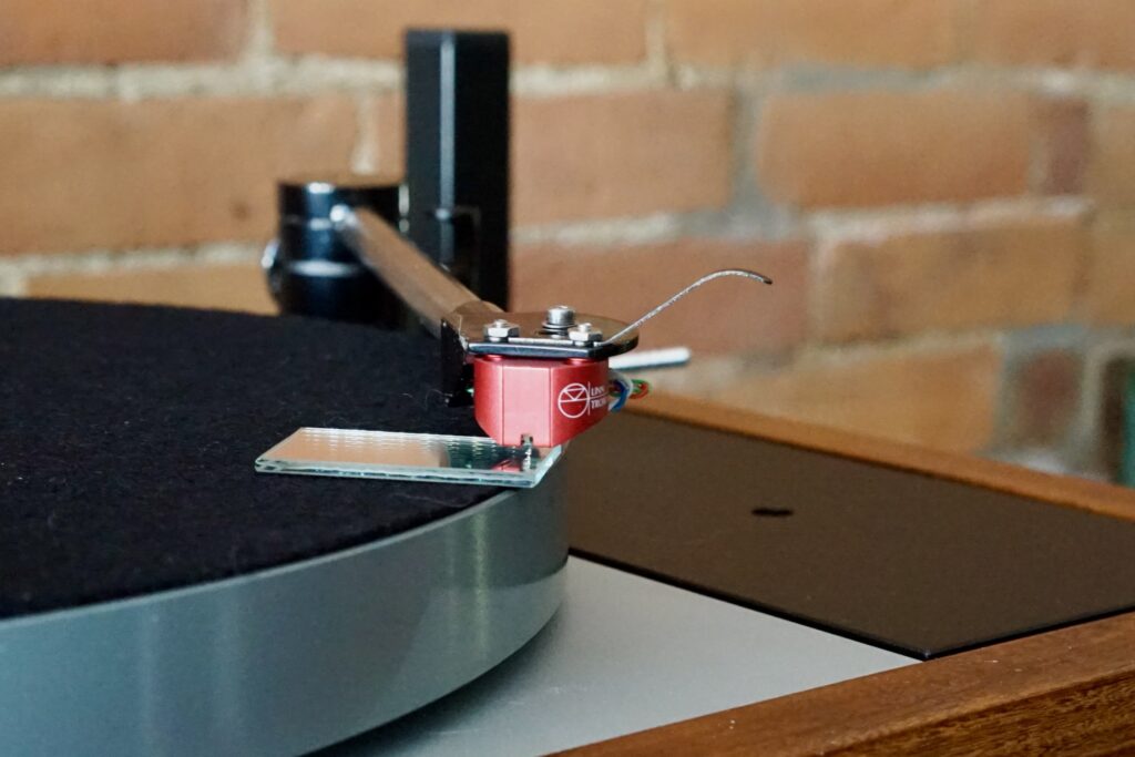
You have it correct when the cartridge cantilever is perpendicular to the record surface, as viewed from the front. You can check this with a mirror or with the reflective surface of a CD (I use two to get them up to the right height.)
Set the overhang.
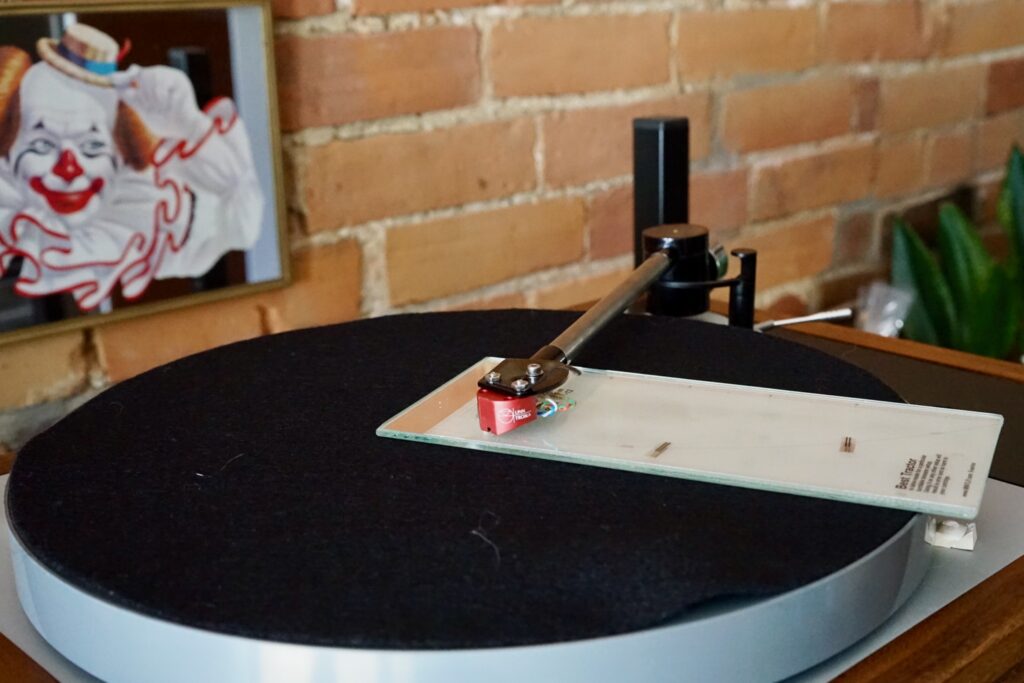
Use an arc protractor appropriate for the Javelin geometry (effective length is 229mm, spindle distance to pivot is 211mm, cartridge offset 24 degrees, 18mm overhang — all the same as Linn arms) to set the overhang. Make sure the stylus exactly traces the arm on your protractor.
Turn the eccentric main bearing pillar as necessary to make adjustments. This is no different than moving a cartridge in headshell slots: rotate the pillar away from the spindle to reduce overhang, and rotate it toward the spindle to increase it. Make sure not to raise or lower the pillar as you do so, as that will change VTA.
4 Comments
Join the discussion and tell us your opinion.
Thanks so much for putting this together! All the content is top notch and photos often end up as desktop backgrounds I like them so much! Such a great arm and well worth the time in set up, and is actually no more difficult than any other that I have owned.
Hey, Adam, you’re co-author of this guide, no need to thank me! I’m planning on revising this a bit over the weekend with photos that more accurately show how things look at particular steps… You know, for the thousands of people out there looking for instructions on how to build their Javelins 🙂
Yep, excellent work!
So an arm that is as rare as unicorn pee gets the best most though set up guide of any, feels fitting! Great job and thx for the kudos for all of the 5.2% of this that I might have been responsible for! Great photos which help lots. I hope other manufacturers take note and send you more arms to set up and do guides for!